USS Hornet CV-8 - 1/350
-
Rodrigues Vaz
- Plastimodelista
- Mensagens: 1442
- Registrado em: 09 Jul 2008, 19:49
- Localização: Niterói / Rio de Janeiro
Re: USS Hornet CV-8 - 1/350
Prezado Júlio,
Uma pequena contribuição.
http://picasaweb.google.com.br/rodrigue ... sHYzNPn9QE#
Rodrigues
Uma pequena contribuição.
http://picasaweb.google.com.br/rodrigue ... sHYzNPn9QE#
Rodrigues
-
Rodrigues Vaz
- Plastimodelista
- Mensagens: 1442
- Registrado em: 09 Jul 2008, 19:49
- Localização: Niterói / Rio de Janeiro
Re: USS Hornet CV-8 - 1/350
Depois de avaliar as fotos, verifiquei que a roda de proa do kit deve sofrer um trabalho de desbaste pra ficar mais fina.
-
Júlio Urubu
- Admin.
- Mensagens: 2515
- Registrado em: 21 Dez 2006, 11:09
- Localização: Niterói
Re: USS Hornet CV-8 - 1/350
Amado Mestre e Guru! Obrigado pelas fotos, mas que porra vem a ser "roda de proa"? Isso é navio, não é um carro 
Estou pensando em levar esta jaca pra você ver amanhã....
Estou pensando em levar esta jaca pra você ver amanhã....
Vade retro goiabão! 
-
Rodrigues Vaz
- Plastimodelista
- Mensagens: 1442
- Registrado em: 09 Jul 2008, 19:49
- Localização: Niterói / Rio de Janeiro
Re: USS Hornet CV-8 - 1/350
Prezado Júlio,
Tá saindo a nova proa.
http://picasaweb.google.com.br/rodrigue ... oXDy72AiwE#
Rodrigues
Tá saindo a nova proa.
http://picasaweb.google.com.br/rodrigue ... oXDy72AiwE#
Rodrigues
-
Júlio Urubu
- Admin.
- Mensagens: 2515
- Registrado em: 21 Dez 2006, 11:09
- Localização: Niterói
Re: USS Hornet CV-8 - 1/350
Nos reviews internacionais deste kit a única crítica é justamente a proa... Eu não ia mexer mesmo, por isso pensei em fazer linha d'agua, mas como o amigo se "prontificou" em fazer uma nova..... 
Valeuzão!
Não esqueceu de fazer o enciaxe dentro do casco para receber os parafusos não né?
Valeuzão!
Não esqueceu de fazer o enciaxe dentro do casco para receber os parafusos não né?
Vade retro goiabão! 
-
Rodrigues Vaz
- Plastimodelista
- Mensagens: 1442
- Registrado em: 09 Jul 2008, 19:49
- Localização: Niterói / Rio de Janeiro
Re: USS Hornet CV-8 - 1/350
É meu amigo,
Tem mais coisa errada:
Pelas fotos, o bordo de ataque das pás dos hélices não são circulares, as bolinas são maiores e as bordas dos escovéns são menores.


Abraços
Tem mais coisa errada:
Pelas fotos, o bordo de ataque das pás dos hélices não são circulares, as bolinas são maiores e as bordas dos escovéns são menores.
Abraços
-
Júlio Urubu
- Admin.
- Mensagens: 2515
- Registrado em: 21 Dez 2006, 11:09
- Localização: Niterói
Re: USS Hornet CV-8 - 1/350
Vade retro goiabão! 
-
Júlio Urubu
- Admin.
- Mensagens: 2515
- Registrado em: 21 Dez 2006, 11:09
- Localização: Niterói
Re: USS Hornet CV-8 - 1/350
Rodrigues, baixa este livro aqui, sobra a classe Yorktown, tem ótimas fotos!
Warship Pictorial 09, Yorktown Class Carriers
http://www.zshare.net/download/wp-s-rar.html
password: farposst.ru
Warship Pictorial 09, Yorktown Class Carriers
http://www.zshare.net/download/wp-s-rar.html
password: farposst.ru
Vade retro goiabão! 
-
Júlio Urubu
- Admin.
- Mensagens: 2515
- Registrado em: 21 Dez 2006, 11:09
- Localização: Niterói
Re: USS Hornet CV-8 - 1/350
Rodrigues, o erro da proa é muito grave..... Eu sabia que tinha lido algo sobre ser "virtualemnte incorrigível", e por isso que era indicado montar na linha d'agua mesmo.
Olha só isso aqui:
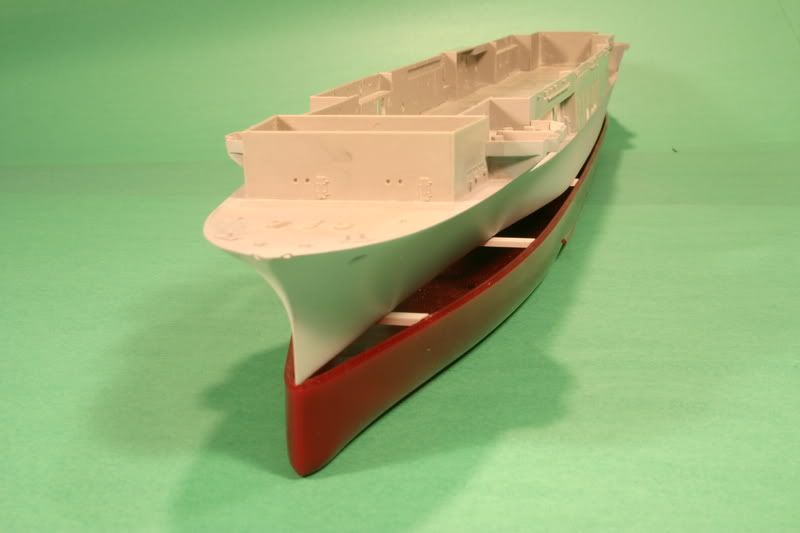
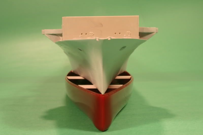
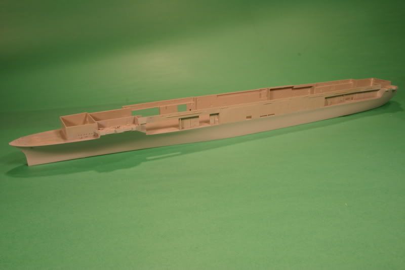
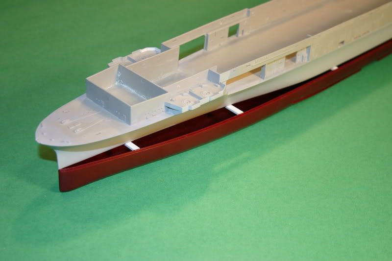
Olha só isso aqui:
Correcting the Trumpeter hull
Postby Mike Sills » Sun Mar 25, 2007 9:11 pm
(I've seen a number of posts now where folks have mentioned trying to correct the Trumpeter hull. The following is a bit long (it was written as an article, but never published). It describes the method I used to rebuild the hull. I am posting it here, with the hope that someone may find it useful. The photos show the corrected upper hull placed on the kit's mishapen lower hull to illustrate the scope of the errors.)
Correcting Trumpeter's CV-8 HORNET Hull
“…the hull is where you begin when you build either a ship or a model and it has to be true.”
-Robert Sumrall
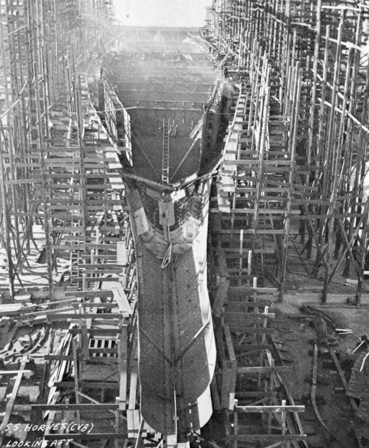
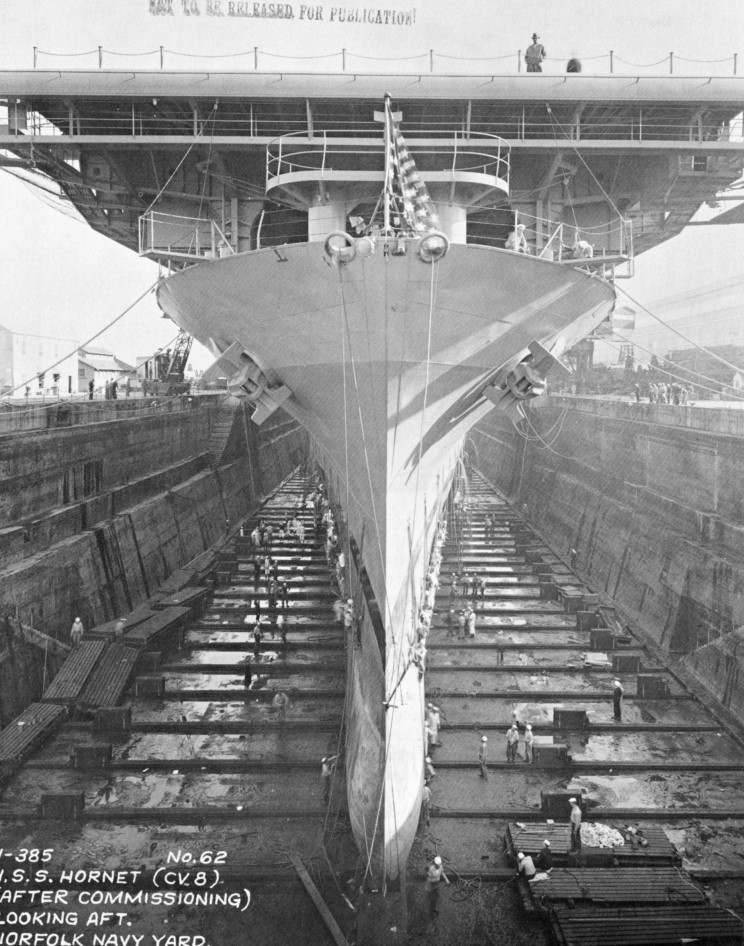
Trumpeter’s hull, while dimensionally accurate at the hangar deck level, is misshapen in cross-section throughout its length due to excessive beam at the waterline. The kit completely misses the radical tapering of the lower hull towards the bow and stern. This results in errors in all of the complex curves of the hull sides. The error is greatest in the forward third of the hull, and it is this area which critics refer to when they state that the shape of the “bow” is inaccurate.
A bit about the prototype. The design of a warship must balance three elements; speed, protection, and striking power. With the CV-5 YORKTOWN class, the U.S. Navy elected to maximize striking power (largest possible flight deck) and speed (large propulsion system). In order to stay within the specified displacement certain compromises were required in the hull design. Norman Friedman's superb U.S. Aircraft Carriers: an Illustrated Design History discusses in detail how this was accomplished. To accommodate the desired length of the flight deck while retaining adequate mid-ship beam for the machinery spaces it was necessary to reduce the hull’s volume at the bow and stern. The beam of the lower hull was drastically reduced both fore and aft, resulting in sharp hull lines that were a key characteristic of the class. While aesthetically pleasing, it rendered them vulnerable to flooding and stability problems. (The two war losses, YORKTOWN and HORNET, succumbed primarily to torpedo damage.)
Comparison of the model with a waterline plan-view of the real hull reveals gross errors in the kit. The beam is excessive at the waterline at every point, resulting in hull sides that are much too vertical. Beneath the forward hangar the curve of the waterline should reverse and become concave. It is here that the dimensional errors are greatest, exceeding 1 1/2 inches (that’s 45 feet in 1/350 scale). This area of the hull is more than twice as wide as it should be. How did Trumpeter get it so wrong? Speculation has it that they copied Blue Water Navy’s 1/350 resin HORNET which suffers from similar hull shape inaccuracies. Jeff Herne and Michael Vorrasi did a comparative review, concluding that while the Trumpeter kit is not an exact copy, the similar errors make it likely that the BWN kit was used as a reference in lieu of actual documentation.
If Trumpeter wanted a 3-D reference, they would have been much better off looking at the old Revell box scale kit. Its details are crude but the hull is outstandingly accurate. It’s currently re-released (Revell-AG kit 5014 “Battle of Midway Carrier”), so if you can get your hands on the old dinosaur, it’s a wonderful reference.
Defenders of the kit have rationalized that the errors are minor, are not noticeable, and are very difficult to fix. Unfortunately, only the last is true. If they really were minor, fixing them would be easy, it is difficult because the errors exceed the thickness of the plastic.. As for being unnoticeable, once you are aware of what the hull should look like the inaccuracies became impossible to ignore. Accepting them is a personal decision, and many fine modelers have done so. But rationalizations will not correct the flaws and so I undertook to rebuild.
I built a waterline model, so I won’t address the lower hull section. It would be difficult to salvage the kit part; I think a scratch built hull bottom would probably be required.
The magnitude of the error varies along the hull’s length, so different construction techniques were employed where appropriate. Mid-ship, the sides should not be vertical, but flare from the waterline up. They can be reshaped, and with some good backing the kit plastic is just thick enough to handle this. The stern is more complicated, since correcting the outline here will require completely grinding through the kit plastic in places. Solid filler will need to be packed inside. The forward hull has the greatest errors. Simply put, they are beyond correction. All of the hull below the forward hangar and forecastle decks will be lost in the rework of this area, and must be fabricated from scratch.
Materials are a matter of preference. I like to work with styrene and cynoacrylate (superglue), but epoxy putties and wood could be used instead and the techniques would be approximately the same.
From the stem, measure back 12” along the hull sides. Make a vertical mark here on each side. (Everything forward of this mark from the hangar deck down will have to go, but don’t cut yet.) Next, take the hull waterline plate and on its bottom mark out the correct waterline outline. Scribe an accurate centerline and cross sections at right angles. Attatch it to the aft part of the hull, up to the vertical marks you made on the hull sides. Do not bond it to the forward part, since that will be cut away.
From the middle working aft, start reinforcing and bracing the inside of the hull sides, particularly at the bottom where the waterline plate meets the hull. Be very generous. I used lengths of Evergreen .250x.125 styrene, bent to follow the kit’s contours and bonded with liberal applications of gap-filling superglue. Test fit your hangar deck sections frequently, to make sure there is no interference and to insure that your reinforcement isn’t pulling anything out of alignment. Keep working all the way back to the stern. Here you must add extra depth and height to this interior “planking”. Alternatively, you could build up this area with epoxy putty, but I like the strength that big slabs of styrene provide.
Trim the waterline plate to its correct contours This is harder with the plate in place on the hull, but the advantage is that you’ve added a lot of strength and rigidity, and you can still beef up the interior structure if it looks to be inadequate.
Attach the hangar decks now for still more rigidity, because it is time to cut loose the forward hull. Starting at the bow below the forecastle deck, on each side make a long horizontal cut just below the deck level, back to a point where it intersects with the hangar deck. Here you’ll need to make a slight vertical jog, and then continue to cut back to those vertical marks you made at 12 inches. Everything forward of this between the waterline plate and decks can now go bye-bye.
For the new forward hull I considered using traditional building methods such as bread-and-butter and plank-on-frame. Eventually I opted for a compromise that used features of both. I built a frame using bulkheads attached to a centerline, then built up bread-and-butter style stacks of styrene in between them. This technique ensured accuracy without compromising strength or rigidity.
Hull plans should be consulted to make the cross-section bulkheads from .040 sheet styrene. These will ensure level decks and true hull alignment, as well as establishing the shape of the hull sides. Make sure everything is level and square before continuing. Lengths of .250x.250 styrene were then stacked in butcher-block fashion, in “step” from the waterline to the deck to conform roughly to the curve of the hull sides. These can be gently bent laterally to conform. They should project beyond the bulkhead dimensions externally. Don’t hesitate to double them internally as necessary. The 5”/38 gallery sponsons will be reshaped so provide adequate internal backing. The correct curve of the hull will require that the outer edges of the forward hangar and fore decks actually form part of the new hull, so be sure they are firmly joined to the styrene stack. Use a solid block of styrene for the upper bow. To ensure a sharp, sturdy stem, make this from a strip of brass stock.
With a cutting head in a motor tool, rough shape the hull by carving away the overhangs where the butcher blocks project from the hull sides. Then put a sanding drum on a 3/8” adjustable speed drill, and at slow speed, shape things further, using the bulkheads as a guide. Shape the remaining kit hull sides to blend in. The sides of the mid-ship section should be less vertical, with a slight “tulip” flare just below hanger deck level. As you move aft the new waterline profile will establish how the vertical curves of the stern should taper. There should be a “crease” where the aft 5”/38 gallery sponsons join the hull at the hangar deck level. External cross-section templates will help establish the correct shapes at specific points and maintain symmetry. Refer to photos of the real ship and “eyeball” the kit at matching angles to determine shapes between these points. I can’t emphasis enough how useful the Revell hull is as a 3-D reference.
Do the final shaping by hand, using progressively finer grit sandpaper wrapped on curved shapes to match the hull (I find old C and D cell batteries and hobby paint bottles useful).
Fill…. sand…. prime…. sand….re-fill….sand….re-prime….sand….sand…..sand…..
Really stupid mistakes I made that you should avoid:
1) I initially underestimated how much of the forward hull would be completely lost, and had to splice in extra styrene sections. The directions above account for my error and should save you from this.
2) I didn’t always provide adequate backing, and ground right through my “corrections”. More splicing of styrene. Do not skimp.
3) When stacking the styrene to build the forward section, keep everything “square” and level. Do not be tempted to angle the styrene blocks to conform to the angles of the hull sides. You’re not building plank-on-frame. It’s more important to get good solid joints, or you’ll pay by doing a lot of filling.
One other weakness of the kit is the fit of the 5”/38 galleries. The splinter shielding should align with the hull contours, so I attached them and the adjacent hanger bulkheads at this point, and re-worked the joints to achieve a smooth transition.
New hawse pipes can be made by drilling holes and inserting plastic tube. Fittings such as degaussing cables, external fuel lines, and portholes (or their cover plates) must be added. These details will be different depending on which of the three ships you are modeling and the specific time frame. As built, all three ships were fitted with a forward hangar deck catapult, which accounts for the sponsons on the hull at that location. HORNET and ENTERPRISE had these removed after Midway.
The way I went about it is certainly not the only way it can be done, but I am satisfied with the results. Is it worth the effort? For me, yes. The payoff comes when I look at the model, and see the sleek lines of the real ship rather than a bulky chunk of plastic.


Vade retro goiabão! 
-
Júlio Urubu
- Admin.
- Mensagens: 2515
- Registrado em: 21 Dez 2006, 11:09
- Localização: Niterói
Re: USS Hornet CV-8 - 1/350
SAbendo então o que procurar, procurei e encontrei. E pior que o cara tem razão... 




Vade retro goiabão! 
-
Júlio Urubu
- Admin.
- Mensagens: 2515
- Registrado em: 21 Dez 2006, 11:09
- Localização: Niterói
Re: USS Hornet CV-8 - 1/350
Tenho procurado plantas, mas não acho. Até agora o melhor que consegui forma fotos de um livro com todas as plantas do Hornet.


Vade retro goiabão! 
Re: USS Hornet CV-8 - 1/350
Uai! A Trumpeter faz um navio deste tamanho e com um erro deste tamanho também?!?!
Acho melhor fazer ele afundado!!!
Brincadiera, Júlio, mas eu faria sem a base.
Brettas
Acho melhor fazer ele afundado!!!
Brincadiera, Júlio, mas eu faria sem a base.
Brettas
-
Rodrigues Vaz
- Plastimodelista
- Mensagens: 1442
- Registrado em: 09 Jul 2008, 19:49
- Localização: Niterói / Rio de Janeiro
Re: USS Hornet CV-8 - 1/350
Prezado Júlio,
Fique calmo quanto as alterações necessárias pra transformar o teu
navio o mais próximo possível da realidade. Elas são possíveis de se
fazer e algumas já estão em andamento. O casco inferior foi alterado conforme os planos de linha originais e colado ao casco superior.
"Não se esqueça que estamos fazendo o navio a quatro mãos"
Abraços
Rodrigues
-
Júlio Urubu
- Admin.
- Mensagens: 2515
- Registrado em: 21 Dez 2006, 11:09
- Localização: Niterói
Re: USS Hornet CV-8 - 1/350
Confio no meu engenheiro 
É que eu achei que o erro fosse apenas a espessura frontal da proa, aí quando atentei pro drama fiquei até com pena de você
É que eu achei que o erro fosse apenas a espessura frontal da proa, aí quando atentei pro drama fiquei até com pena de você
Vade retro goiabão! 
-
Júlio Urubu
- Admin.
- Mensagens: 2515
- Registrado em: 21 Dez 2006, 11:09
- Localização: Niterói
Re: USS Hornet CV-8 - 1/350
Ontem encomendei o restante da "air wing" do Hornet, vou lotar o bichão com sua força total 
E olha só os detalhes que encontrei do Tokio Raid e que nunca havia atentado para tal, nem nunca vi ninguém representar isso!
É sabido que 5 F4F estavam a postos na proa para decolagem imediata em caso de ataque ao CV-8, mais as aeronaves do CV-6 Enterprise. Agora, aeronaves misturadas com as B-25??
Notar dois Dauntles na esquerda da 1º foto, e uma cauda listrada na direita, atrás das B-25, e na segunda foto o F4F qe só víamso a pontinha da cauda.


Estou bem mais animado de fazer o Hornet em viagem para Tokio, e não mais lançando o ataque como havia inicialmente penssado
E olha só os detalhes que encontrei do Tokio Raid e que nunca havia atentado para tal, nem nunca vi ninguém representar isso!
É sabido que 5 F4F estavam a postos na proa para decolagem imediata em caso de ataque ao CV-8, mais as aeronaves do CV-6 Enterprise. Agora, aeronaves misturadas com as B-25??
Notar dois Dauntles na esquerda da 1º foto, e uma cauda listrada na direita, atrás das B-25, e na segunda foto o F4F qe só víamso a pontinha da cauda.


Estou bem mais animado de fazer o Hornet em viagem para Tokio, e não mais lançando o ataque como havia inicialmente penssado
Vade retro goiabão! 
Quem está online
Usuários navegando neste fórum: Amazon [Bot] e 0 visitante